Overview
The TDT is a unique wind tunnel facility that is optimized for aeroelastic, dynamic, or high-risk testing. A unique feature is the ability to use either Air or R-134a heavy gas as a test medium. R-134a has a higher density, lower viscosity, and lower speed of sound than air. These gas properties enable the construction of a sub-scale model with a lower natural frequency and heavier structure in order to match the full-scale dynamic characteristics. As a result, these properties simplify the construction and greatly reduce the cost of dynamically-scaled models. For certain classes of large vehicles, the TDT is the only facility capable of testing sub-scale models with the appropriate dynamic similitude to a full-scale vehicle. Additionally, the TDT is the only large transonic facility that offers: direct model viewing from the control room; airstream oscillation; high-frequency model pitch oscillation; rapid speed reduction capability; or a model catch screen to protect the drive fan in the event of a model failure. A secondary benefit of R-134a is that the reduction of viscosity and speed of sound enables larger Reynolds number and Mach number simulation at lower dynamic pressures. This results in the ability to model full-scale aerodynamics at a fraction of the loads, tunnel power requirements, and corresponding risk and model cost versus what is possible in air. Therefore, the TDT has also been used for many non-aeroelastic tests that wish to capitalize on the benefit of these gas properties, the dynamic data system, and/or the facility’s willingness to conduct high-risk testing.
TDT Facility Overview Video 
Link to GFTD TDT Video
Characteristics
| Wind tunnel | Large, closed-circuit, continuous-flow, single return |
|---|---|
| Test section | 16 feet x 16 feet with cropped corners |
| Test Medium | R-134a or Air |
| Main drive power | 30,000 HP, two speed ranges |
| Mach number range | 0 to 1.2, continuous |
| Total pressure range | 0.01 to 1.0 atmosphere, continuous |
| Reynolds number (max) | 9.6 million per foot (R-134a), 3 million per foot (Air) |
| Dynamic pressure (max) | 550 psf (R-134a), 320 psf (Air) |
Features
- Excellent model visibility from control room
- Rapid tunnel shutdown for model safety
- Safety screens for fan protection
- Several model support (mount) systems
- Sidewall Oscillating Turntable – high frequency model pitch oscillation
- Sting-mounted remote roll capability
- Airstream oscillator (gust generating) system
- R-134a reclamation / purification system
- Test section / plenum isolation valves
Flow Quality
The flow quality of the TDT is exceptional for a large transonic facility. Numerous studies have been conducted evaluating: turbulence content; flow angularity; boundary layer size; Mach number distribution; and wall interference effects. Additionally, statistical testing is periodically accomplished with a centerline probe and a check standard model to verify consistent test procedures and tunnel performance. Test to test comparison of the check standard model data has shown repeatability in drag measurements for different installations to be approximately one drag count for conditions where balance axial force is loaded to at least 50% of the calibrated load.
Turbulence: Compared to other large transonic wind tunnels, TDT has one of the lowest turbulence levels. For more information about flow turbulence and comparisons with other wind tunnels, review the following reports: TDT x,y,z Turb. w/ unsteady pressure, TDT y,z Turb. w/ hotwire, TDT x Turb. w/ hotwire (LWP 799), AEDC transition research![]() , AEDC transition research part II, NTF turbulence w/ unsteady pressure.
, AEDC transition research part II, NTF turbulence w/ unsteady pressure.
Angularity: Compared to other large transonic wind tunnels, TDT has one of the lowest values of flow angularity. A flow angularity study conducted at TDT showed the measured angularity to be below the instrumentation accuracy of +/- 0.3 degrees in both vertical and lateral directions. Additional testing was accomplished by Boeing evaluating angularity with variations in lift coefficient of a representative aircraft model. The Boeing study concluded that uncorrected flow angularity was on the order of 0.02 degrees. Additionally, check standard model data indicates uncorrected angularity to be on the order of 0.02 degrees. For more information about angularity, review the following reports: TDT angularity, Boeing TDT research.
Boundary Layer: The boundary layer of the TDT varies slightly with Mach number, dynamic pressure, and tunnel wall location. In general, a significant velocity recovery (greater than 95%) occurs after 6 inches and a 99.5% recovery occurs at approximately 8 to 13 inches. For more details regarding TDT boundary layer, review the following reports: TDT boundary layer, LWP 799.
Test Section Mach Number Distribution: The TDT has a fairly constant Mach number distribution throughout the test section. At subsonic Mach numbers, the constant Mach region extends as much as 30 feet. For supersonic Mach numbers, the constant Mach region is approximately 12 feet. For more information regarding Mach number distribution, review the following reports: TDT Mach number, LWP 799.
Wall Interference Corrections: The TDT is a slotted wall facility with 3 slots on the floor and ceiling and 2 slots on each side wall that produce an openness ratio of 4.4%. Based upon classical correction theory presented in AGARD AG-336, the floor and ceiling slot geometry is optimized to eliminate up-wash error. Similarly, the sidewall slots are optimized to eliminate blockage errors. Additionally, slotted test sections typically produce minimal buoyancy error. As a result, wall interference is minimal in the TDT for moderately sized models over a wide range of Mach numbers. A wall interference study was conducted for a representative transport wing that spanned approximately 55% of the test section width. In this study, it was concluded that models of similar size and planform produce interference free data below Mach 0.88: TDT Interference. For large models with significant blockage ratios, wall corrections may be necessary to obtain quality aerodynamic performance data. The following report contains corrected data for a parachute model tested in TDT that produced a blockage ratio of 8%: DGB Parachutes. The wall correction method used is based upon measured wall pressures and applies the technique described by Mokry in AGARD CP-335![]() . A wall correction code is available for use at TDT based upon the technique described by AGARD CP-335. Future research at TDT will be aimed at refining and validating the wall-pressure-signature-based interference correction method.
. A wall correction code is available for use at TDT based upon the technique described by AGARD CP-335. Future research at TDT will be aimed at refining and validating the wall-pressure-signature-based interference correction method.
Data System
The TDT data system is capable of acquiring synchronized dynamic data for 256 analog channels that can be calibrated with linear or non-linear curve-fits and have wind-off tares applied as desired. Additionally, power can be supplied to instrumentation at various voltage levels with remote sense capability. All analog signals are anti-aliased filtered, conditioned, and amplified as necessary. Available scan rates vary depending upon the channel count and the configuration of each particular test, but the nominal scan rate is 500 samples per second. An Electronically Scanned Pressure (ESP) system series 8400 is also available and capable of scanning thousands of steady pressure readings. ESP pressure modules are currently available to support several hundred pressure readings at various pressure ranges from +/- 0.3 psi to +/- 15 psi. Typically scanned at 10 samples per second, the ESP steady pressure data is acquired simultaneously with the dynamic data. Additionally, a circular archive system continuously records data that is available for writing to a file, and can capture the previous minute of data for all channels at the full scan rate when selected by the user. The circular archive is particularly useful for recording unexpected dynamic events. Connections are also available for a customer supplied data system. Supplemental data systems have been used in order to acquire aeroacoustic data at high frequency, or to support closed-loop aeroservoelastic testing such as active flutter suppression or gust load alleviation. Finally, a suite of post-point analysis software is available that provides dynamic analysis functions such as: fast Fourier transform; power spectral density; moving-block damping analysis; and multiple-point multiple-channel time history plotting.
Supported instrumentation includes but is not limited to: full-bridge or partial bridge strain gauges; pressure transducers; piezoelectric and piezo-resistive accelerometers; Q-Flex angle accelerometers; position transducers; thermocouples and many other instrumentation types. The data system also has a built-in balance interaction calculation with angle of attack and model weight tare corrections that are applied to the dynamic data and are time correlated with other data quantities.
A new data system is under development for use at TDT that will have an increased scan rate, adaptability for an increased channel count, and increased reliability.
Model Mount and Support Systems
Several model mount systems are available for use at TDT and include an electric sidewall turntable, articulated hydraulic sidewall turntable, floor turntable, sting, cable-mount system, and supporting hardware for helicopter or tilt-rotor aicraft. Additional model support systems include motor-generator sets to provide conditioned electrical power, a chilled water cooling system, hydraulic power, an airstream oscillating system, and high pressure air or R-134a for model systems.
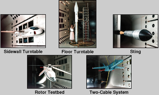
Five model mount systems: sidewall turntable, floor turntable, sting, rotor testbed, two-cable system. Note: the sidewall turntable can be either electrically operated, or a hydraulically actuated oscillating turntable.
Airstream Oscillation System
Operating Boundaries
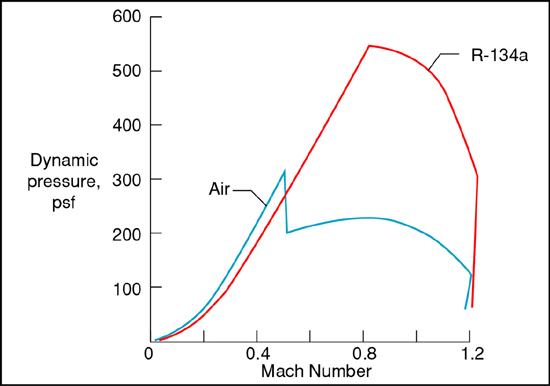
- Maximum dynamic pressure is 550 psf (R-134a), 320 psf (Air)
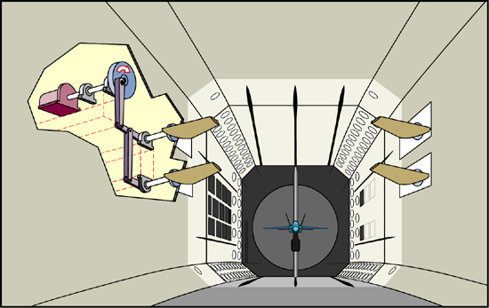
Cutaway Drawing of TDT
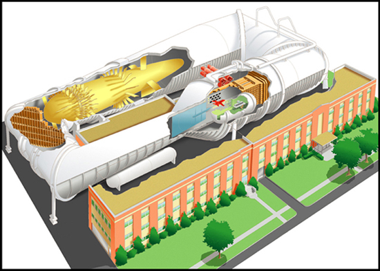
Cutaway Drawing of TDT
Plan View Drawing of TDT
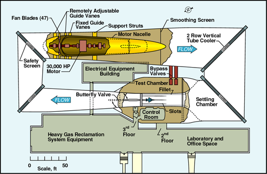
Plan View Drawing of TDT
Cross Section Drawing of TDT
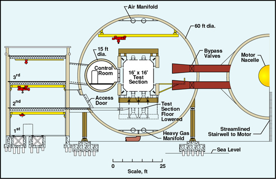
Cross Section Drawing of TDT
TDT Logo
The TDT logo design is based on the unique cross section (square with cropped corners) of the TDT test section. The blue color blend on the logo depicts the atmosphere below and space above and represents the wide range of atmospheric and space vehicles tested in the TDT over its 40-year history. The stylized vehicle in red is representative of aerospace vehicles and its oscillating exhaust contrails suggest “dynamics.” The integration of the TDT letterforms illustrates the continuous flow through the tunnel
History
Langley cultural resources website on the TDT and its predecessor.